

Updated: 07-Jan-2026
Hellmut Walter was a research chemist specialized in chemical engines for torpedoes.
![]()
“Walter logo”
-He began working on rocket propulsion for aviation and in 1935 founded HWK, “Hellmut Walter Kommanditgesellschaft,” his own company to carry out this work.
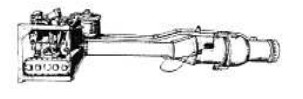
“A first chamber of the HWK 109-500”
-In the CL chamber diagram, point 1 shows the peroxide inlet.
-Point 2 shows the catalyst inlet, point 3 shows the fuel and oxidizer mixing chamber, and point 4 shows the Laval-type outlet nozzle.
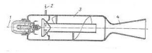
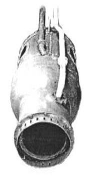
“The CL chamber in practice”
-Here, point 1 shows the oxidizer inlet, point 2 shows the oxidizer inlet, and point 3 shows the outlet of the tube for measuring the chamber pressure.
-Point 4 is where the coolant enters the engine and, after circulating through the double wall of the combustion chamber and the nozzle, returns through port 5.
-The first useful engine was the RI-202, with 400 kgf of thrust, operating with T-Stoff (80% hydrogen peroxide and stabilizer) and Z-Stoff (calcium permanganate).

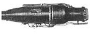
“HWK109-500”
-The RI-203 would be the basis for the HWK109-509. The RII-203 version already had a maximum thrust of 750 kgf and was the one tested on the Me-163 A and B prototypes.
-Considered "Cold" engines, they had adjustable thrust between 150 and 750 kgf.
-The RI-210B was mounted on the Enzian I and III (see DVK) and designated as the HWK109-502.
-It used Br-Stoff and SV-Stoff, pressurizing the tank with T-Stoff and Z-Stoff, and produced 1,500 kgf of thrust.
-The HWK-109-500 was widely used to assist takeoff in various aircraft that required it due to insufficient power of the main engines, overloading, or short or elevated runways, and in hot weather.
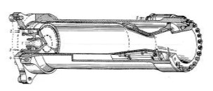
“Two aircraft with Rato Walter boosters installed”
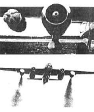
“Rato ready and takeoff with assistance”
-The construction of these boosters included the nacelle where the engine and its controls were located, in addition to the tanks.
-In other words, it was a complete "Power Egg."
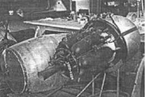
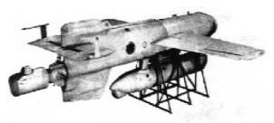
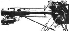
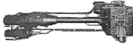
“Assembling the HWK109-500”
-The following illustration shows the engine being installed under the aircraft's wing.
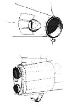
-Since the engine has a parachute at its nose and a tether attached to the wing, it pulls a pin that will deploy the parachute when the engine detaches.

“Parachute Installation”
-The 500-series engine produced approximately 500 kgf of thrust.
-The next engine of this type was the HWK109-501, which we will show next.
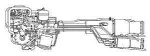
-We see two diagrams of the HWK109-500 and HWK109-501.
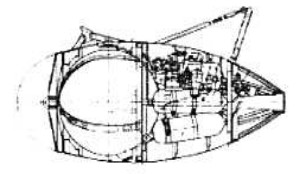
"Walter HWK 109-500"
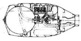
“Walter HWK 109-501”
-The second engine produced significantly more power than its predecessor, delivering 1,500 kgf of thrust.
-The Walter engine was also used on the Henschel Hs-293 radio-guided air-to-surface missile. It was the HWK109-507.

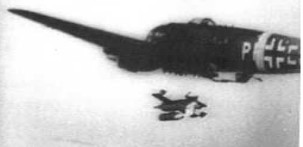

“From top to bottom: The Walter HWK109-507. Installation
beneath the HeS-293. Launch and en route to the target”
-The HWK109-507 operated using Z-Stoff and T-Stoff, producing 590 kgf of thrust.
-It was highly effective on this missile, sinking several ships.
-The RI-211 gave 1,700 kgf of thrust but was considered dangerous due to its fuel mixture: Z-Stoff was replaced by C-Stoff, a highly reactive mixture, requiring the fuel tanks to be clearly separated.
-The RII-211 would be the HWK109-509A-0, with 150 to 1,500 kgf of thrust, considered a "hot" engine and the prototype of the A-1.
It was mounted on the Me-163B, with its first flight in May 1943.
“Me-163 Komet”
-Now fully integrated into the HWK109-509 models, the A-1 with 150 to 1,700 kgf of thrust, the same as the 509A-2.
“Two HWK109-509A, initial”
-With the HWK109-509A-1, we had a flight duration of 3 to 4 minutes at maximum power, and with variable thrust control, it could be extended to 8 to 12 minutes.
“Chamber with coolant line”
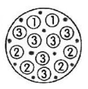
“Multiple C-Stoff outlets in the chamber”
-We have the minimum thrust: 1, medium: 1+2, and maximum: 1+2+3.
-To control the thrust, there were several inlets in the chamber, and depending on whether the C-Stoff arrived through one, two, or three branches, it could be operated according to the needs.
“Cover installed and removed”
-With the intake cover in the chamber, we see the arrival of the different pipes that will control the thrust.
-The C-Stoff enters the chamber from the turbopump through the clear pipe shown in the previous column.
-It passes through the double wall of the venturi and the chamber to return to the valve box, which will control the return flow through the three pipe branches.
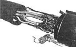
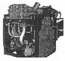
“Control Box”
-The control box houses the electric pump for starting the engine, which will deliver the T-Stoff to the evaporator.
-There are generated the gases that will drive a double turbopump: one for the T-Stoff and the other for the C-Stoff.
-Once the T-Stoff turbopump generates pressure, it will feed the evaporator, closing the circuit.
-The turbopump's exhaust outlet is visible below the control assembly, which we see under the fuselage of the Me-163 during takeoff.
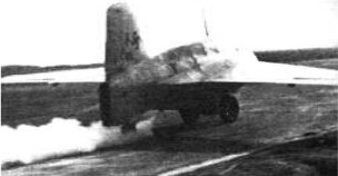
“ME-163 aircraft beginning its takeoff run”
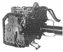
-In the next view, we can see the three-valve body—at the top—which will divide the flow to the combustion chamber, allowing the pilot to control the thrust.
“Control box, another view”
-The HWK109-509B, derived from the RII-211, had the main rocket engine and a secondary or cruise chamber.
-Essentially, it was an A-1 and therefore a descendant of the A-0.
-With 150-1,700 kgf of thrust in the main chamber and 100-300 kgf in the auxiliary chamber.
“HWK109-509B”
-This engine was practically the A-1 with the second cruise chamber added.
-The C model was similar but more powerful, with 150-2,000 kgf and 100-400 kgf thrust, based on the A-2.
“Diagram and photo of the HWK109-509C”
-From the exterior appearance, we can tell if the Me-163 has a B or C engine, or if it is an A model (-0, A-1, or A-2).
“Two types of outlets” (PiP)
-The HWK109-509C was intended for the Me-263 aircraft. And for the Ju-248, the Ba-349 Bachem Natter, although the latter would use the E version.
-The HWK109-509D was an engine like the A-2 but with separate parts and longer intake ducts to the combustion chamber.
“HWK109-509E”
-The E variant of the 509 model was used on the Bachem Natter, a piloted rocket-powered aircraft with special missions such as jamming bomber formations and launching volleys of small air-to-air rockets.
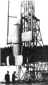
“Vertical Take-Off Bachem”
-The HWK109-509E was also known as the HWK109-509A-2E. It produced 150-1,700 kgf of thrust. The Natter took off using Schmidling solid rocket boosters.
-The 109-509S-1 and S-1, known as Heimatschützer I and II, with thrusts of 1,700 kgf and 2,000 kgf respectively, were intended to support the Me-262. They were derived from the A-2 and C engines.
-The Walter HWK109-559 was also intended for the Natter.
-The HWK109-729 was a small rocket engine designed for the Schmetterling missile.

“Walter HWK109-729”
-The Schmetterling missile was the Hs-117. The engine consumed B and SV-Stoff to deliver 375 kgf of thrust.
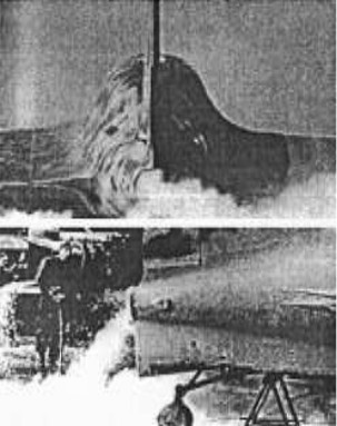
“Two Me-163s”
-The instability of the rocket engine fuels is noticeable during the preparation for ignition.
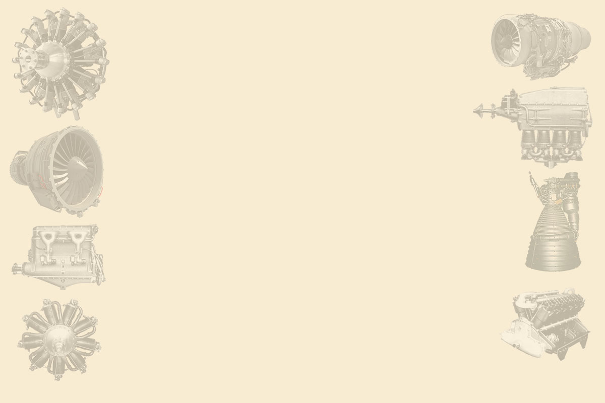
Another aspect of Walter's work involves ramjet-rockets, or the use of engines built with ramjet thrust boosters.
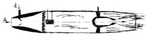
“Walter ramjet-rocket engine”
-Air intake A directs the engine's forward motion. Fuel enters at point 1 and, after passing through a stabilizing grid, is ignited by an electric igniter.
-The rocket engine serves to initiate flight and, once airborne, to increase thrust.
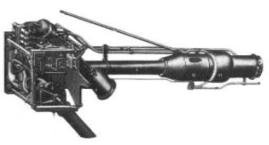
-In addition to the latest received information, a photograph of Walter's rocket engine, the HWK 109-739, intended for the Enzian, has appeared.
“Walter HWK 109-739”
-At the end of WWII, among the wreckage of the destroyed Luftwaffe, all sorts of materials were found mixed together as scrap metal in areas like the one shown, located in Bavaria.
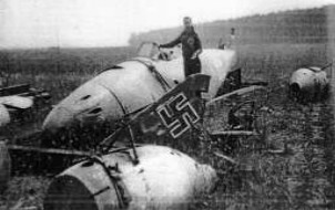
“Some Luftwaffe Remains”
-Among these remains, we see at least two Walter HWK 109-501 booster engines.
-On the other hand, two new illustrations of the HWK 109-500a have been located.
-The first of these is in the RAF Museum in Cosford, with its complete wing mounting structure and, at its base, a cutaway combustion chamber from an identical -500a engine.
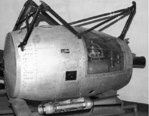
“HWK 109-500a, without parachute”
-And the other 500a shown is in the German Luftwaffe Museum. Unrestored.
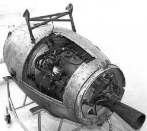
“HWK 109-500a, in Germany”
-We also find the Walter 109-509a-1 at the Luftwaffe Museum, complete and restored.
-And also another HWK 109-509c at the Cosford Museum in England.
-Engines that we constantly see in the various models of the Messerschmitt Me-163 “Komet,” an aircraft designed to intercept Allied bombers.

“The HWK 109-509a-1, in Germany”
“The HWK-109-509c, in England”
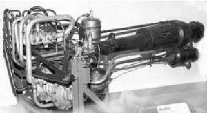
From Appendix 6: Regarding the rocket motor model for takeoff assistance, the RI-202 is mentioned in the main text.
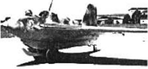
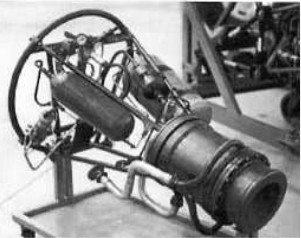
-We have now received a photograph of the RI-202B that is on display at the San Diego Museum in California.
“Walter RI-202B”
-It was designed for assisting heavy aircraft in takeoff (Rocket Assisted Take-Off = RATO) on short runways or when fully loaded.
-It could be jettisoned using a parachute installed in the engine's nose (see main text) after approximately 39 seconds of operation.
-This time is deduced from a fuel consumption of 4.17 kg/sec, carrying approximately 133 kgf of hydrogen peroxide in the integrated spherical tanks.
-On the top of the assembly, above the combustion chamber, was an adapted 5 kgf tank of potassium permanganate. As we can see, it carried 138 kg of fuel, out of a total of 499 kg for the entire assembly.
-This assembly was completely and suitably faired, and was called the “Kraft Eier” or “Power Egg” in English.
-The most well-known example is the one used on the world's first jet bomber, the Arado 234B.
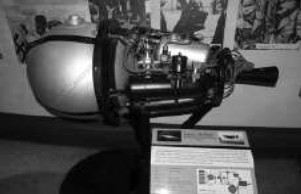
-And now, a photograph of a Walter engine mentioned in the main text, but for which no illustration was available at the time of writing.

“Photo of the Walter RI-203 (R-1-203)”
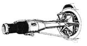
From Appendix A2/6: Helmut Walter made the K-1 combustion chamber for the 109-507 engine mentioned in the main text.
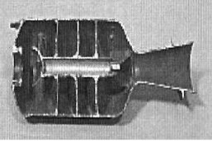
“K-1 Chamber”
-The 109-507 engine was used by the Henschel Hs-293 anti-ship air-to-surface missile. The central duct and the divisions were designed to promote a more homogeneous mixing of the "T-Stoff" (hydrogen peroxide) and the "Z-Stoff" (permanganate) catalyst. The combustion resulted in high heat and steam expelled through the nozzle.
Motores de WALTER, HELLMUTH
Model: 109-500
Arquitecture:
Chambers:
Fuels:
Feed System:
Ignition:
Thrust:
Weight:
Model: 109-501
Arquitecture:
Chambers:
Fuels:
Feed System:
Ignition:
Thrust:
Weight:
Model: 109-502
Arquitecture:
Chambers:
Fuels:
Feed System:
Ignition:
Thrust:
Weight:
Model: 109-507
Arquitecture:
Chambers:
Fuels:
Feed System:
Ignition:
Thrust:
Weight:
Model: 109-509
Arquitecture:
Chambers:
Fuels:
Feed System:
Ignition:
Thrust:
Weight:
Model: 109-559
Arquitecture:
Chambers:
Fuels:
Feed System:
Ignition:
Thrust:
Weight:
Model: 109-719
Arquitecture:
Chambers:
Fuels:
Feed System:
Ignition:
Thrust:
Weight:
Model: 109-729
Arquitecture:
Chambers:
Fuels:
Feed System:
Ignition:
Thrust:
Weight:
Model: 109-739
Arquitecture:
Chambers:
Fuels:
Feed System:
Ignition:
Thrust:
Weight:
Model: RI-201
Arquitecture:
Chambers:
Fuels:
Feed System:
Ignition:
Thrust:
Weight:
Model: RI-202
Arquitecture:
Chambers:
Fuels:
Feed System:
Ignition:
Thrust:
Weight:
Model: RI-210B
Arquitecture:
Chambers:
Fuels:
Feed System:
Ignition:
Thrust:
Weight:
Model: RII-203
Arquitecture:
Chambers:
Fuels:
Feed System:
Ignition:
Thrust:
Weight:
Model: RII-211
Arquitecture:
Chambers:
Fuels:
Feed System:
Ignition:
Thrust:
Weight: